| Author: | Robert W. Brewer |
|---|---|
| Date: | 2006-08-08 |
Abstract
I upgraded my house with a structured wiring project to distribute network, phone, and TV signals. In this document I describe some of my rationale for various design choices and my experiences. I also provide a detailed list of materials, tools, and supplies I used to help when planning a similar project.
Contents
- Structured Wiring Overview
- Motivation
- Goals
- Photos
- Wired vs. Wireless
- Cat6 vs. Cat5e
- Simple Telephone Patching
- Cable Bundling
- Solid vs. Stranded Wire
- T568A vs. T568B
- Patch Panel Pro and Con
- Cable Labeling
- Tips and Tricks
- Tools and Supplies Used
- Cabling and Wiring parts used
- Costs and Benefits
- Suppliers
- Links
Structured Wiring Overview
Structured wiring is a style of wiring where bundles of several types of cables all go to the same place. Typically a "home run" (star) topology is used. This means that each cable run goes back to a central location, referred to as the CWP (Central Wiring Point). By using a star configuration with a CWP, it is easy to reconfigure the wiring connections for various uses. Typically for an ethernet network, the CWP would contain a network switch. For TV, video, or RF signals, the CWP often contains a splitter and possibly an amplifier.
Although not required, often each wall plate in a structured wiring system will have an identical configuration. The advantage of this is simplicity. All wire bundles are the same, and every structured wiring wall plate has the same services. The disadvantage of this is that the location of a single wall plate in a room may not be ideal for every service on that wall plate. For example, you may want telephone service on one side of the room near where the couch is positioned, and cable TV service on the other side of the room where the TV is located.
For more information on structured wiring, I recommend the excellent Structured Wiring How To. My goal with this web page is to augment that excellent how-to with some of my own experiences and thoughts on this sort of project.
Motivation
What reasons are there for doing a wiring project? In my case, there were several reasons:
- My wireless networking has reliability and speed issues compared to just plugging in an ethernet cable. I wrote more on this topic in the Wired vs. Wireless section.
- My home, although it's not ancient, for some reason does not have a phone or TV outlet in the bedroom I'm now using as my office. I could use a cordless phone, but it still seems like a serious oversight to have a bedroom without a phone jack.
- Past cable TV installers committed horrific acts against my home. For example, they ran multiple cables around on the outside of the house, then drilled holes through the side of the house and poked them through. When they wanted to put cable into the next room over, they just laid it on the floor, drilled a hole clear through the next wall, and kept on going.
Goals
I decided to do a structured wiring project to solve the issues in the Motivation section along with some others while I was at it. These were the main goals:
- Create a CWP (Central Wiring Point) in my garage near the breaker panel and incoming phone service
- Reroute the incoming cable TV service to the CWP via the attic. For some reason the cable service comes to the opposite side of my home from the electric and phone service. My guess is that the local cable monopoly did this to save themselves about $3 worth of coax cable the first time they committed the horrific acts against my home.
- Run structured wiring from the CWP to each bedroom (3) and the living room.
Each wall plate has the following:
- 2 Cat6 cables with RJ45 (ethernet) jacks
- 1 Cat6 cable with an RJ11 (telephone) jack
- 2 RG-6 quad shield coax cables with F connector (TV) jacks
- Remove all the horrific external and internal cable TV wiring and patch the holes
- Correct some of the higgledy-piggledy phone wiring done by the previous owner
- Increase my geek cred to extraordinary new levels
Photos
Here are some photos of the finished project as well as while it was in-progress.
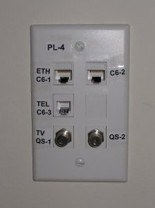
The finished wall plate. This is all that is visible in the main living spaces of the house.
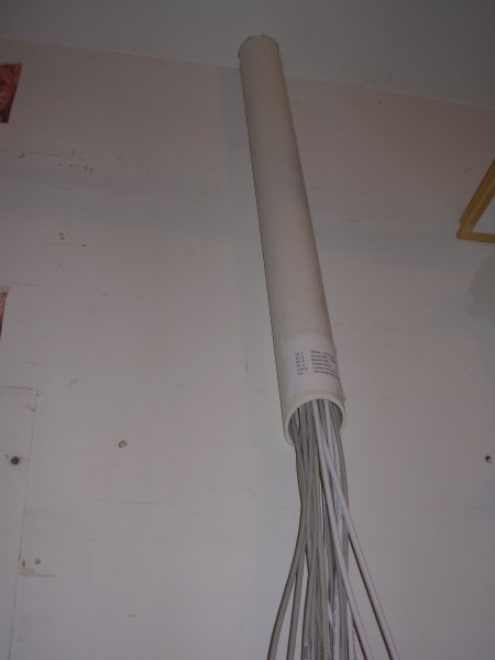
The finished CWP, located in the garage. Note how simple it is: a single PVC pipe. Currently there is no shelving, no patch bay, or anything. The few cables currently in use are connected below, the others are left to dangle. For now I'm not even using a network switch at the CWP, but just a cat6 coupler. My cable modem and router are currently in the office.
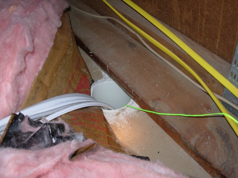
The PVC pipe for the CWP from inside the attic.
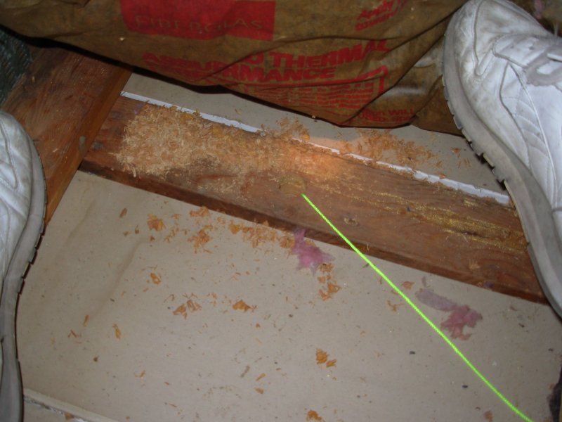
The hole in the top of the wall in the attic where cable will be pulled up through. The flourescent green pull string is coming out of the hole.
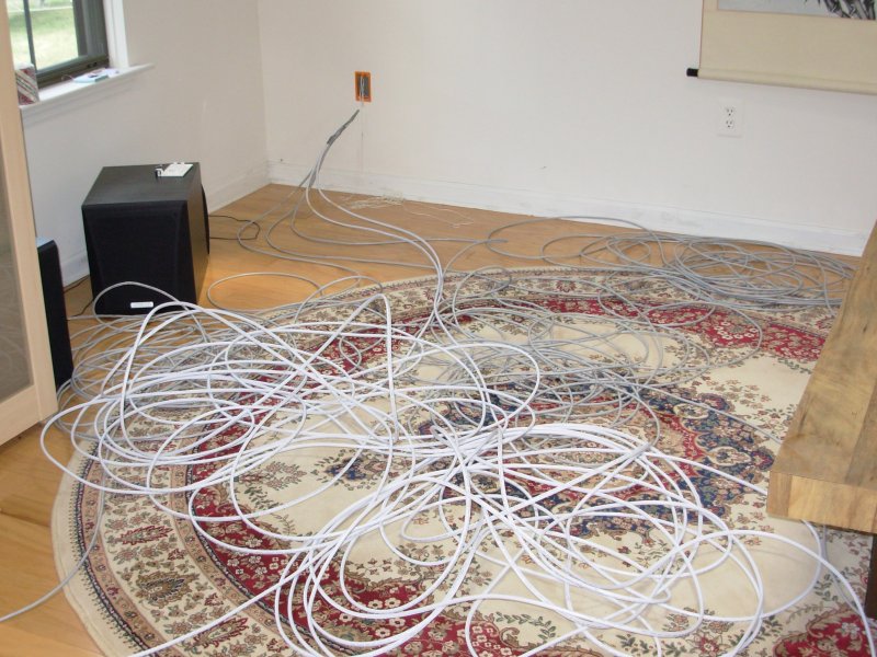
About 500 ft of RG-6 quad shield and cat6 cable waiting to be pulled into the attic.
Wired vs. Wireless
Reliability
I have a wireless router and a wireless card in my laptop. It's pretty convenient. Unfortunately, it cuts out when I use my microwave oven. It also cuts out when I use my cordless phone. It also cuts out every now and then for unknown reasons, perhaps due to interference down the block. I could solve most of these issues by purchasing new wireless devices. I could probably get wireless devices in the 5.8 GHz band to avoid the microwave, and if I'm lucky they would even avoid each other in that band. If I got really lucky, whatever other interference there is would be lesser in that band and my wireless reliability issues would be solved. Or they might not, and I will only really know that after I have a boatload of new gear.
Speed
802.11g with an access point is half duplex. It's also a shared medium, like a hub instead of a switch. I usually only see an 11 Mbps or 22 Mbps bitrate where my devices are located. Couple that with other protocol overheads, and the overall throughput of my wireless connection is not so great.
The Right Tool for the Job
On the rare occasions that I move my laptop from the desk, the convenience of wireless is great. And when somebody visits and wants to use my internet connection, it's another wireless love fest. But most of the time, I think it would just be more reliable and faster if I plugged my laptop into a wired ethernet port when it is sitting on my desk.
Cat6 vs. Cat5e
Under the right conditions, Gigabit ethernet (Gig-E) can run over cat5e cabling. Gig-E is only just now being rolled out, so what advantage does cat6 cabling have? Cat6 will be able to support 10 Gigabit ethernet (10Gig-E). Why, pray tell, do I need the capability of 10 Gbps data transfers throughout my house? I don't know the answer to that, but I do recall a time when Microsoft designed MS-DOS around the assumption that nobody would ever need more than 640 KB of RAM in their personal computer, and today an average laptop has nearly 1000 times that.
But my main reason for installing cat6 cabling today is not so much that I need the extra capabilities of cat6, but that I can get those extra capabilities without much increase in the overall cost of the project. That's because the bulk of the cost is my own installation labor. If I installed cat5e now, and 10 years from now I really want cat6 instead of cat5e, I would have to repeat the most difficult, uncomfortable, and hazardous part of the labor, which is crawling around in my attic. I did consider installing cat6 cabling but terminating it with cat5e connectors. But there again, the time it takes me to terminate the connector wins over the actual price difference. And both the cat5e connector cost and installation time would be wasted if I later upgrade them to cat6. So I felt it was sensible to just start with cat6 everywhere.
But let's be realistic. I'm not going to replace any of my cat5e patch cables with cat6 until I have an actual need.
Simple Telephone Patching
As part of rerouting the old phone cables, I connected them all in parallel to a single cat6 cable (in the attic) that routes to my CWP. The CWP also has my newly installed cat6 phone cables. Because there are only 5 phone cables to connect for the moment, I opted to use 2 standard RJ11 couplers as shown in the figure. One is a 3 female to 1 male coupler, the other is a 2 female to 1 female coupler. By connecting these together all of my cables are connected. Crimping on a few RJ11 connectors and using this scheme seemed cleaner and easier for now than dealing with wire nuts or a punchdown block.
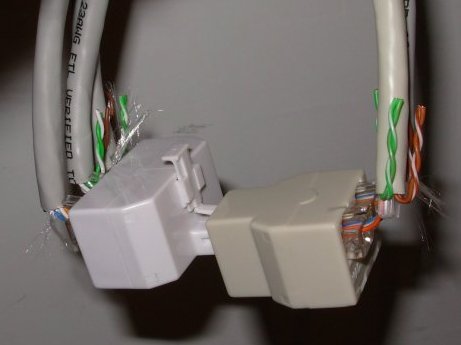
A 3-way coupler connected to a 2-way all-female coupler, which connects 5 phone cables very simply.
Cable Bundling
I used a different method of bundling my cables compared to what is shown in the Structured Wiring Bundling section. I tapered my bundle by attaching a single cable to the pull string, then a second cable about 1 inch further down, the next cable another inch down, and so on. This made it easier to pull the cable through the hole in the top of my wall.
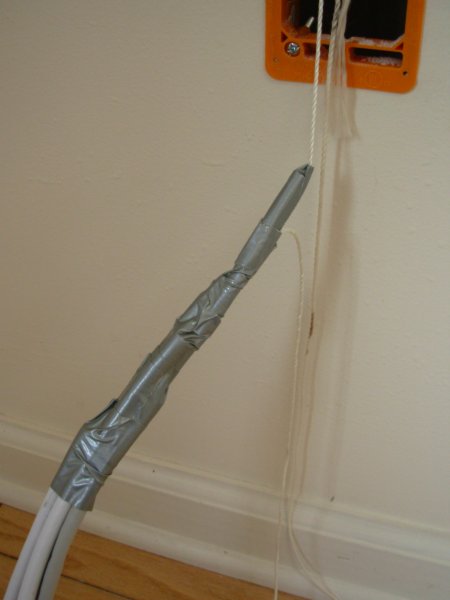
Tapered bundle of cables ready for pulling.
Solid vs. Stranded Wire
Solid core wiring has lower loss. Stranded core wiring is more flexible and can better withstand repeated flexing. Therefore, long, fixed runs of cable should use solid wiring. Patch cables should use stranded wiring.
T568A vs. T568B
I used the T568A wiring standard throughout my installation. If you are starting from scratch, definitely make your runs use the T568A wiring standard, which is what the TIA/EIA standard document recommends. See the Wikipedia T568A entry for details. Also, the US government requires T568A in all federal contracts. You don't have to agree with the US government in various policy matters, but in the area of technical standards, "might makes right."
This is one of the few points I disagree with from the Structured Wiring How To.
Patch Panel Pro and Con
Here's my breakdown of the pros and cons of implementing a patch panel at the CWP as opposed to terminating the wires in plugs and using them directly for connections.
Pro:
- Bomb-proof wiring installation
- More professional looking
- Stranded core patch cables can withstand repeated flexing better than solid core wiring used in horizontal runs
Con:
- More complicated, so more parts to fail and troubleshoot
- Costs more
I chose not to implement a patch panel at my CWP. In a commercial lab environment with cables being changed multiple times per week, the repeated flexing of the wiring may be more of an issue. I don't plan to touch my CWP connections more than a few times per year. Also, it is easy enough to add a patch panel later if I want it. The only work and cost I will have wasted is installing the RJ45 plugs. I won't even have wasted the coax F connector terminations. So my strategy is to wait on installing a patch panel until I see it really is needed.
Cable Labeling
I figure that the cables installed now will stay there for a long time. The signals carried over the cables may change. The purposes of the rooms they are installed in may change. And other cables may be added over time. But those cables will remain where they are. Because of that, I wanted a labeling scheme that would remain constant based on the cable's installed location. One way to do that is to just assign a serial number to each cable (1, 2, 3, 4, etc.). But then I need a separate table somewhere to remind me where each cable goes. Instead, I chose to number the wall plates, and number the cables based on their type. Since all the cables go to the central wiring point, my main concern is where the other end is. Here are some examples of my scheme:
- PL-2:C6-3 - this cable is at wall plate 2, and it is cat6 cable number 3.
- PL-3:QS-1 - QS is quad shield, so this is RG-6 quad shield cable 1 in plate 3.
The labeling on the wallplate itself also has a user-meaningful indication of what signals are currently available on that cable. Examples are ETH (ethernet), TEL (telephone), and TV (cable TV). It looks like this:
| PL-2 | |
| ETH C6-1 | C6-2 |
| TEL C6-3 | |
| TV QS-1 | QS-2 |
Currently there is one slot completely blank on my wallplates, and two slots with cabling and connectors that are not "live".
When documenting my configuration, for clarity it may be necessary to distinguish each end of a cable when describing connections. For those cases, the PL-2:C6-3 notation means the end at the wallplate. I prefix it to indicate the CWP end: CWP:PL-2:C6-3. Maybe it's a scheme only a software guy could love.
Tips and Tricks
- Cable Spools
- Always unroll the cable from the spool. Do not just take the loops from the side of the spool without unwinding the spool. I tested this and learned my lesson the hard way.
- Cable Kinking
- Try not to allow cables to "bunch up". Even cables that have been removed from the spool (or box) properly seem to kink very easily. The kinking can happen anytime there are loops and sections of cable folded back on each other. One way that helps with this is to not pull too much cable into one area at a single time. Try to disperse the loops and foldovers over the largest distance possible and you will minimize the formation of kinks.
- Cable length measuring
- I placed two hexagonal shaped end tables far apart in my living room. I measured the distance between them. I placed my box of cable next to one of the tables. To measure a length of cable I walked around and around the two tables while holding the end of the cable, using the tables like a 15 feet long winding spool. I converted all my lengths into table separation units.
- H-style Cat6, Cat5e, and Cat3 keystone jacks
- CyberXlink sells "H-style" keystone jacks, as compared to "U-style". I find the H-style easier to work with, because the slots for the wires are all in a line. Because of this, there is less need for making correct bends in the wiring pairs.
- Punch down the wires one at a time
- At first I tried to align all wires in the keystone jacks before punching them down. This was a recipe for going very slowly. When I aligned and then punched them down individually it went much faster.
- Don't use grounded quad shield
- Because it was on sale, I purchased RG-6 quad shield that also had a ground wire. I figured I could rip it off. I was able to rip it off, but it added a lot of time to the process of measuring out my coax. Also, because of the small burr of insulation remaining on the cable, the connectors were very difficult to put on. Eventually I realized that this was the problem and I cut the burr off with a sharp knife, but I had already wasted significant time putting on connectors.
Tools and Supplies Used
- Wire cutters
- Lotta wire cutting going on. :)
- Coax wire strippers
- For terminating coax cables.
- Coax F connector tool
- For terminating coax cables.
- Drill and 1 inch spade bit
- For drilling down into top of wall from the attic.
- Punchdown tool
- For terminating network cables in keystone jacks
- RJ45 plug crimp tool
- For terminating network cables in RJ45 plugs
- Wallboard saw
- For cutting holes in drywall to install mudrings.
- Hacksaw
- For cutting PVC pipe conduit for central wiring point.
- Straight and Philips screwdrivers
- For installing mudrings.
- Tape measure
- For measuring cable lengths.
- Braided nylon masonry cord
- For making pull-strings from the attic down into the wall.
- 1/2 ounce teardrop-shaped lead fishing weights
- For dropping the pull strings down through the wall.
- Duct tape
- For bundling cables together when pulling, and attaching the bundles to the pullstrings.
- Masking tape
- For making temporary labels on the cables during the pulling. The final labels are applied when the cables are trimmed to the correct length and terminated.
- N-95 Dust mask
- For crawling around in a dusty attic with fiberglass insulation.
- Eye protection
- For drilling.
Cabling and Wiring parts used
Bulk non-plenum cat6 UTP solid-core cable
Bulk RG6/U quad shield coax cable
Cat6 RJ45 plugs (ethernet)
Cat6 RJ45 keystone jacks (H-style)
Cat3 RJ11 keystone jacks (telephone)
RJ11 plugs (telephone)
Network cable slip-on no-snag booties
F-connector female barrel-type coax keystone jacks
F-connector male coax plugs
Carlon orange plastic low-voltage mudrings
Leviton 6-port keystone wall plates
Leviton blank keystone inserts
4-inch diameter PVC pipe
screw wall anchors
Rite & Wrap cable labels
Costs and Benefits
Labor Costs
Unfortunately I forgot to explicitly keep track of the total time I spent on this project. These are my estimates:
| Task | Hours |
|---|---|
| Reading/Planning | 4 |
| Shopping/Purchasing | 4 |
| Conduit install | 1 |
| Pullstrings/Mudrings | 2 |
| Measuring/Pulling cable | 12 |
| Terminating cable | 12 |
| Rerouting phone cable | 3 |
| Rerouting CATV cable | 2 |
| Documenting | 4 |
| Total | 41 |
Dollar Costs
I spent around $500 on tools and materials for this project.
Suppliers
These are the suppliers I used.
- CyberXlink
- Good prices on bulk network and coax cabling and some keystone connectors. Sometimes they have specials with free shipping. Located in California, something to keep in mind regarding shipping costs. I bought my RG6U quad shield coax, cat6 keystone jacks, F-connector keystone jacks, cat6 RJ45 plugs, and slip-on plug booties from them.
- CompuNetTech
- Also good prices on bulk network cabling and some keystone connectors. Located in North Carolina, something to keep in mind regarding shipping costs. I bought my cat6 cable, cat3 (telephone) keystone jacks, and a cat6 inline coupler from them.
- CableOrganizer
- The only supplier I could find for Rite & Wrap cable labels.
- Home Depot
- I found the local Home Depot store was good for buying tools, some connectors, mudrings, and of course the occassional last-minute item. I purchased the Data Shark coax kit from them, the matching male F connectors, some F connector barrels, the carlon orange mudrings, and
Links
- Structured Wiring How To
- This is a comprehensive must-read for anyone considering home network wiring. Many good ideas in here. My only disagreement is with his choice of the T568B wiring standard, since T568A is preferred.
- How to wire your house for low-voltage signals
- A nice email with some suggestions to keep in mind.
- Wikipedia T568A entry
- Describes the T568A wiring standard with a nice diagram of the pin layout.
- How to Wire a Phone Jack
- Nice diagram showing how to connect cat5e or cat6 UTP wire to a phone jack and to old-style 2-pair telephone wire. Very handy and clear.